I recently took a look at a an interesting internet article about a very fast ST.
https://www.fordmuscle.com/features...kis-exceptionally-fast-10-second-explorer-st/
Being an engineer and relentlessly curious, I'm looking at some of the choices made on that owner's recent modifications and although I'm very impressed at the quality of the welding, I'm less impressed at the exhaust design choices that were made. So, at the risk of criticism, and to offer some insight, I'd like to address a few points about the newest iteration of this build as it pertains to the exhaust.
If we look at the newest rendition, we have new top mounted twin turbos (cool) with external wastegates (cool) feeding into dual 3" exhausts (info from FB page). Incorporated into those 3" exhausts is a true "X" pipe. No matter how it's designed, as an "X" an "H" or some other bridged design, the concept and theory is to "balance" the exhaust flow. Now, for both of you that read my previous posts on this exhaust thread you'll remember that I encouraged smaller pipes, heat retention by minimizing surface area, and the re-introduction of laminar flow after the turbine to reduce backpressure. I also stressed that what might work for an N/A or supercharged engine may not translate to a turbocharged engine.
My previous posts should address why a dual 3" exhaust is not only unnecessary, but actually inhibits performance- unless one is talking about a 1,500+ hp engine. In the case of a 700 hp engine or even a 1000 hp engine, it's not helping anything, but if his goals are higher or it creates a pleasing tone, that's entirely up to him.
View attachment 10658
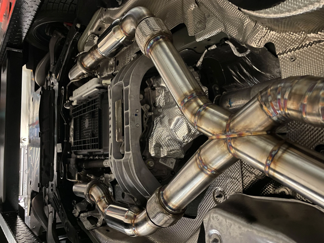
However, the most interesting item is the "X" pipe. Take a look at the link I posted above and ask yourself this question: What is this "X" pipe's purpose?
There are three schools of thought on a "balance pipe", "H" pipe, "X" pipe, etc. The first is that it creates a venturi effect that "sucks" out exhaust from one pipe to the other. Let's explore that a bit. A higher velocity gas in a tube creates a lower pressure than a lower velocity gas- which will exhibit more pressure. Carburetors use this technique to raise the velocity in a tube by accelerating it which creates a low pressure area into which fuel (at atmospheric pressure) is then "sucked" into the airstream. There is no doubt that at low RPMs there could be momentary surges of velocity from each bank- but this depends on the exhaust pulse timing and the pipe length and diameter being appropriately sized. How much racing are you doing at 2000 RPM? So think about it for a minute- which tube, coming from two symmetrical engine banks at 6000 RPM has a higher velocity? Neither. Doesn't that mean that these two "flows" are simply interfering with each other causing turbulence reducing the flow rate?
The second school of thought pertains to vehicles with mufflers after the balance pipe. In this case the thought is that the exhaust "sees" less restriction (pressure) since there are two mufflers rather than one. This scenario actually makes a bit of sense if you have very restrictive mufflers, and the pipes have a small shared area- In that case, a design like this makes sense: The flows have minimal interaction (assuming the co-joined throat is sized correctly) while still allowing some bleed-off when there is indeed a pressure differential. I'd suggest as minimal a bend as possible with a throat area no larger than 1/2 the pipe cross section.
View attachment 10659
The third school of thought involves "pressure wave tuning". In this scenario, we can use the length of a primary pipe (intake or exhaust) and harness the on-off flow of the ICE and an abrupt change of volume in the pipe (intake manifold, header collector, cylinder). The abrupt change in volume causes a rapid rise in pressure, and like hitting a drum head, that pressure "wave" is reflected back along the primary tube path. As the wave reflects, contrary to common sense, it actually causes the flow in the original direction to increase. Depending on the RPM and the length of the primary pipe one can use this phenomenon to increase torque peaks at certain RPM points. You've seen all sorts of "tuned port" intakes and exhaust primaries for 50+ years. This is one of the reasons you see strange bumps and depressions in a dyno chart (all else being equal). The problem is that this potential "reflection" the source (exhaust valve) and has already been pretty much exhausted by the turbine housing or collector to be meaningful.
If you've followed this far, you might be scratching your head and wondering, OK, TMac, that sort of makes sense, but why have I seen dynos that show low-to-mid-range HP gains with those "balanced" pipes?
The answer is the design of those pipes are inherited from a completely different beast that is heavily hot-rodded: the cross-plane V8. Believe it or not, the normal V8 does not fire equally on both banks. Contrary to an even firing V6 like the ST, let's take a typical cross-fire V8 with firing order 1-8-4-3-6-5-7-2. Follow along- left bank fires, right, right (again), left, right, left, left (again), right .... When viewed from each bank's perspective, the cross-plane crankshaft individual exhaust pulses from each bank are not symmetrical- they are "unbalanced". In which case, a well-designed exhaust "balance" mechanism can be used to harness the uneven pressure surges that result. It's just not something applicable to an even fire turbocharged V6 and I wouldn't use an "X" pipe as shown in Kruppa's pics in any case.
Once again, this shows that even something a reputable tuner might espouse while well-meaning might not work for your ST.