Background:
A common issue in these cars in the 2019-2021 build date is a failing ground on the AWD module under the driver’s seat. The metal enclosure of the AWD module is supposed to be grounded by 3 nuts to the body of the car. These standoffs are often covered in paint and in general are just terrible for a proper ground. This failure can be a completely failed ground which means there is an open circuit from the Case to the body of the car. This will cause some set of symptoms, primarily AWD module no longer responding or turning on at all. The failure can also just be an intermittent issue where the symptoms go away and come back occasionally. And finally it can just be that the case has a high resistance path to the body. In this last instance, a multimeter will beep in continuity mode from the case to the body indicating a ground Is present but the resistance is high. The hallmark feature of this issue is that the AWD module gets a lower voltage than all of the other modules. This last case doesn’t seem to be documented anywhere online except in my thread where I diagnosed the issue. In my instance with high resistance ground, it caused the brakes to occasionally fail to work after starting the car and putting the car in gear. VERY SCARY FEELING. Also, I got various frequent ABS codes and random modules failing to respond or getting invalid data. The most worrisome codes it may cause is “transfer case current low” and “transfer case clutches slipping” and “transfer case actuator current low” and “general electrical failure” from the transfer case. And in the ABS module it would report that the transfer case module stopped responding. Every time I scanned for codes i had some different variation of the DTCs.
Diagnosis and Identification:
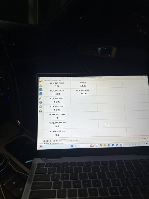
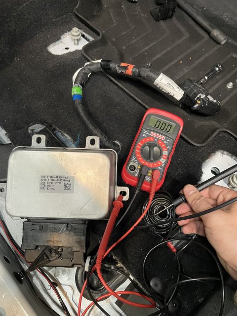
If you can use Forscan on a computer and log data live with the oscilloscope feature, this would tell you more. The AWD module needs to see close to 12V with engine off and 14v with engine on. If you see 8-10v with engine off or 8-12V with engine on, then you likely have a bad ground. Otherwise if the AWD module isn't being found at all in forscan then your ground might be completely failed.
You can put the drivers seat all the way forward and pull the carpet up pretty easily just enough to see the AWD module. Check continuity from the case to the body of the car. You should have 0 ohms resistance it should be a straight shot from ground to the body.
You can also try wiggling the connector on the AWD module to see if the ground clears up. That temporarily resolved my issues. I have read reports of people removing the harness and putting it back on and the issues going away. When logging live in forscan you can see the voltage correct itself when the ground is restored.
Known issue acknowledged by Ford:
Ford has issued a couple TSBs that i was able to find. Originally they issued a TSB to replace the modules when this happened. They were constantly changing them out and the issues would come back later. Then they discovered the grounding issue. So they issued a (seemingly temporary) TSB to remove the seat and de-pin the ground wire from the harness and splice in a new dedicated ground that terminated at a ring terminal to an M6 bolt in the body of the car under the seat. Finally, it seems to me that this TSB no longer exists anywhere in the Ford database. Now they just fall back to the original TSB to replace the modules but i’m guessing the newer modules have some updated provisions to handle the grounds better internally so it’s not an issue. Personally I don’t want to spend a thousand bucks for the dealership to replace the AWD module when it just needs a ground. So I performed the TSB to add a ground to the existing module.
My Guide for performing TSB 23-2061 for Adding Ground to existing Module:
The official TSB from ford (that no longer exists in their databases) is here: https://www.explorerst.org/attachments/ford-tsb-23-2061-pdf.31859/
things you will need:
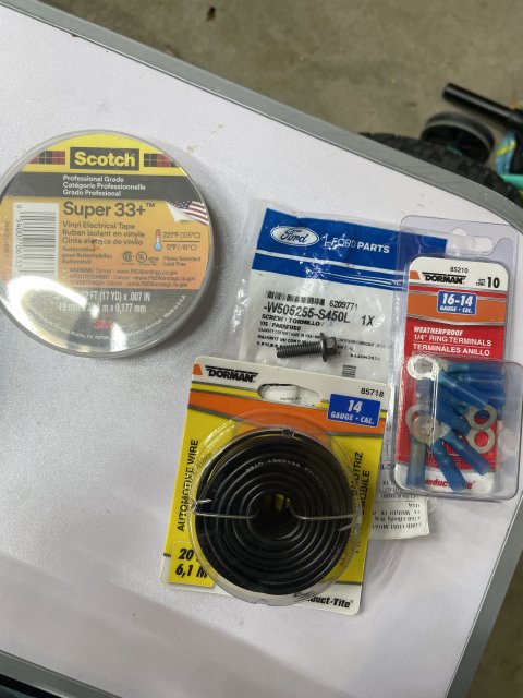
the bolt from ford is M6. I used the official Ford bolt but use whatever M6 bolt you like. A 1/4” or M6 ring terminal, i prefer the heat shrink ones. Electrical tape. Some good quality wire. I opted for 14awg. I wouldn’t really go thinner than that. Hard to know what current is expected through it without measuring it in different scenarios. I haven’t smelt anything burning yet so I think 14 AWG should be good (; lastly, you need some way that you feel comfortable to connect this wiire to the ground pin of the AWD module. Honestly this could be as simple as another ring terminal on the nut of the AWD module mounting stud. But because I didn’t fully understand the internal workings of the module I opted to follow the TSB as close as I could. You might be able to get away with a tap splice to the ground wire. If you know the part numbers and know where to get the female pins for the harness that would be the most ideal way. I personally chose to solder the 14AWG wire directly to the existing ground pin. This felt like the best way in my opinion because it means you are not relying on the current flowing through the thin factory wire. But do whatever you feel comfortable with. I’m not responsible for you messing up your harness connector.
getting started:
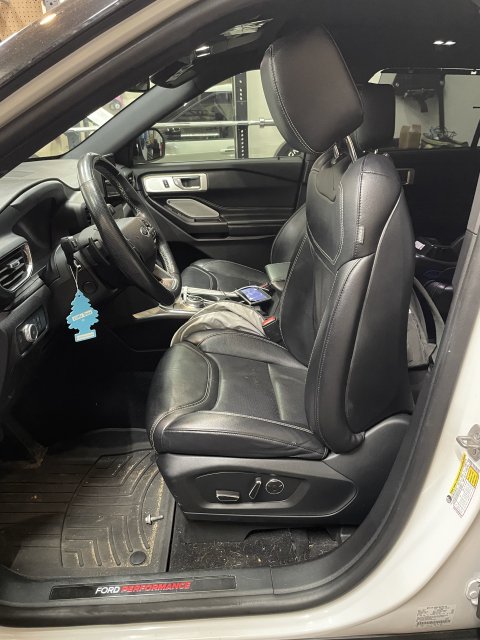
Move the backrest all the way forward so it fits through the door. Then move the whole seat all the way back to expose the front frame bolts.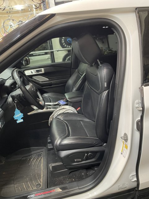
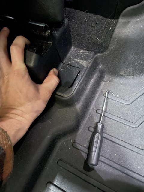
then remove the plastic covers and unbolt. It’s 13mm.
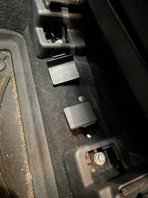
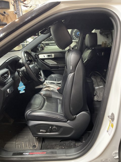
Then move the seat all the way forward to expose the two rear frame bolts. Remove the plastic covers and unbolt. 13mm again. an extension will help.
now the seat is loose but there is two cables you need to worry about before moving the seat out.
before disconnecting the connectors you need to move the seat halfway forward so the frame rails fit nicely under the butt of the seat. This just helps you fit it through the door. Then disconnect the negative terminal of the battery so you don’t throw a bunch of codes for tampering with the electronics.

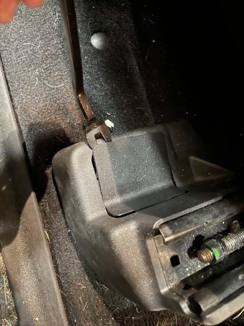
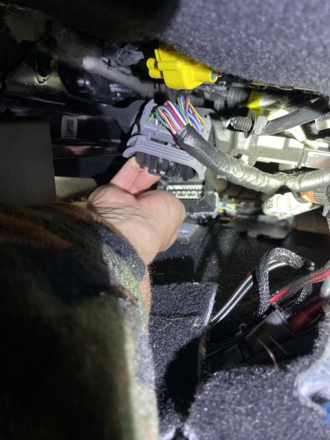
 Under neath the seat up under the butt, you have a chunky connector. Press into the connector in the center and there is an arm you need to swing out once the center is pressed in. It’s pretty easy once you figure out how it works.
that body harness is also secured to the seat with a plastic clip so you need to pry it out of the mounting hole.
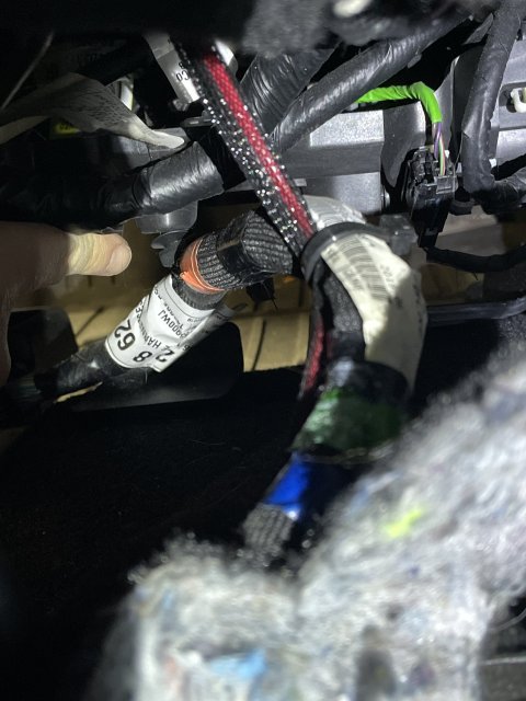
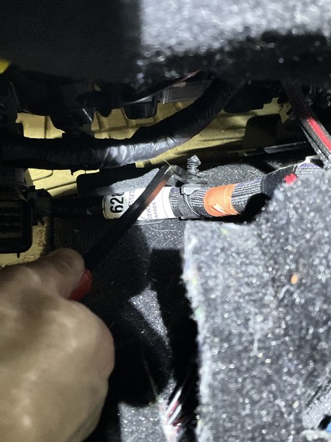
the following cables look aftermarket and bunk as heck so I don’t know if you will have them… but if you do, cut all the zip ties and expand the cable to it’s full length. There is NO connector to disconnect here… thankfully my cables were super long so i was able to remove the seat still with it attached.
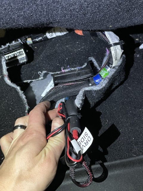
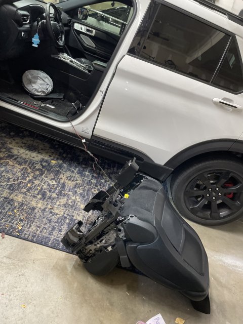
 You’re ready to remove the seat now. Optionally you should be able to just push the seat back onto the second row if you fold the second row down. If you proceed to remove it entirely, Be careful not to scratch the plastic trim on the floor or the B pillar. Maybe put a blanket down! It’s heavy but doable alone.
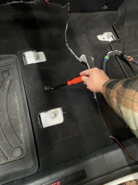
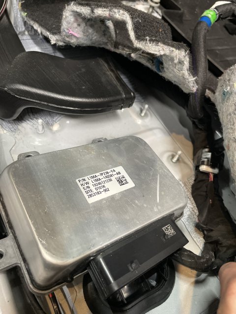
expose the beam and AWD module under the carpet. Pull up that one plastic clip.
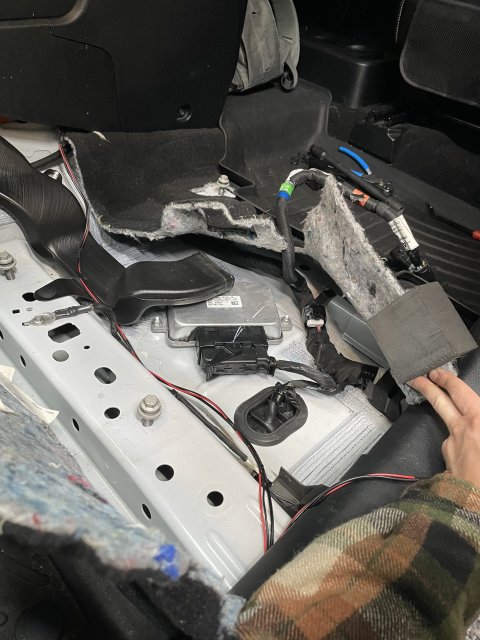
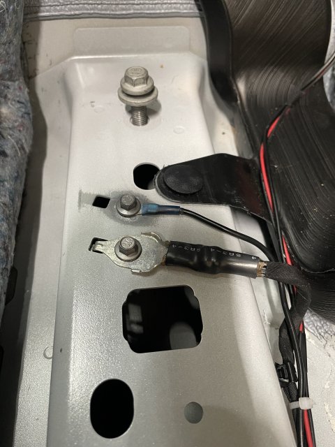
here you can see the terrible studs Ford relies on for grounding. You don’t need to remove the module but I did just to get a good look for the photo.
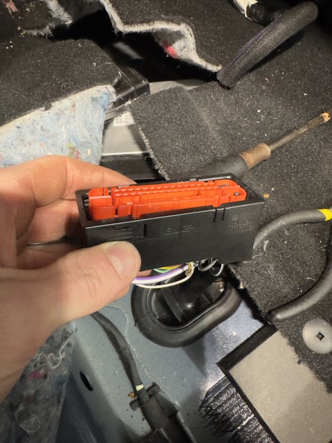
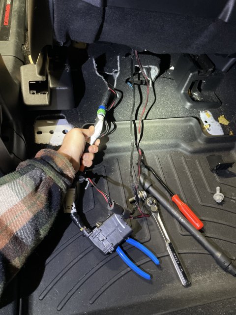
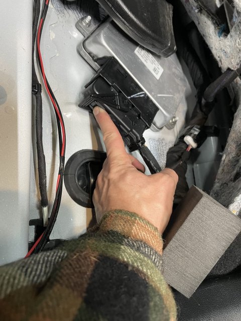
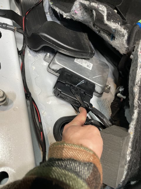
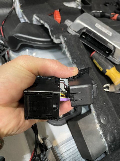
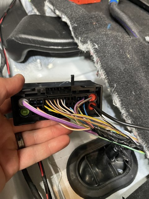
press this center tab and then swing the arm out. Pull the connector off.
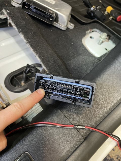
this is the pin you will want to depin if you plan to follow my same method of soldering the 14awg wire to the pin.
to remove the red locking Block, it’s not too bad. Use a small flathead to get under the red inside the channel and pry it up. You should squeeze and apply hard pressure with your other hand to the outside of the black housing to help prevent breaking it when prying against it. I broke mine in a few spots but the connector still operates and locks on very good. So it’s not life or death here if you crack something. There are two little channels where you can put the flathead into and there is a good way to get under the red. Use those sides first since the other two of the 4 channels dont give you as mich of a ledge to catch with the screwdriver. It’s really not too bad i thought it was going to be a lot harder.
once you get the red block out, this housing comes off easy. Remove it by pressing this tab and pulling off.
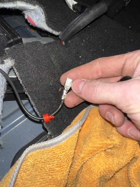
to depin the black and white ground wire pin, its pretty easy too. In between the top and bottom pins you can see the little locking tab deep down holding it in. just pry the plastic tab away from the pin and pull the wire from the back and it will come out. You will want to cut and peel the electrical tape and wrap the factory puts on, expose as much wire as you need. This is how far i went:
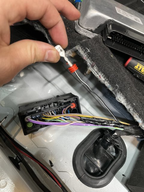
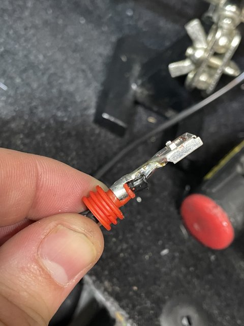
i opted to save the red seal thing and just jam the wire through the center. I used a sharp spike tool i had and inserted it through the center and then fed the wire through after the spike. I dont think you need the rubber seal it just helps with corrosion and strain relief but this connector shouldn't see harsh conditions so do what you like.
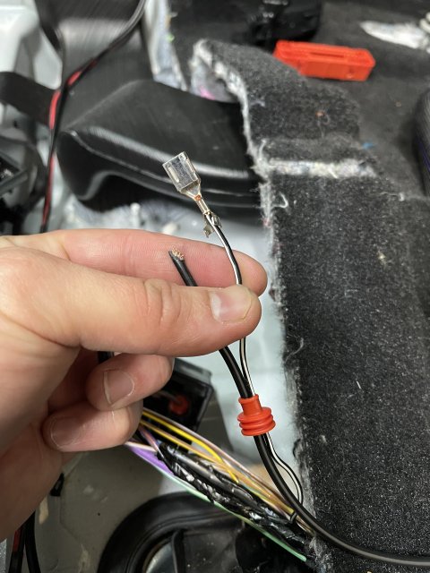
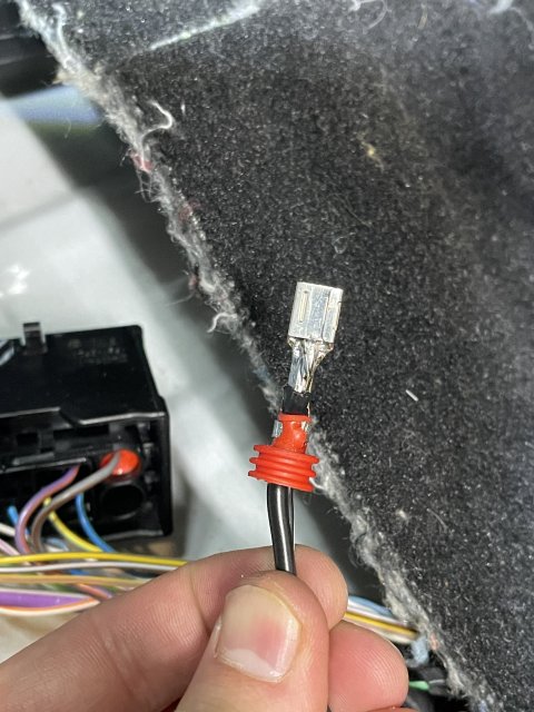
Solder the new wire to the pin and keep the old wire there. Get it nice and hot, make sure everything is flowed nicely, dont leave a cold joint. Thankfully the connector housing gives you a lot of room for the extra space the solder and wire takes up.
insert the wire to it’s home in the connector listen for the snap of the locking tab, pull to make sure it is secure.
Press the Red locking block back in, it will snap nicely.
Now you want to just give the wires some slack and electrical tape up tightly back to the body harness make it look nice and this will help protect the wires at the pins. Then reinstall the housing and zip tie it on again. just put it back how you found it basically. Check the connection from the AWD module case to the wire you just added.
Then you need to crimp and heatshrink the ring terminal. Measure out how much wire you need and zip tie it in a few spots to the factory harness. You also need to sand the paint (and underlying primer) to expose raw metal on this beam. This is where you will insert your m6 screw and ring terminal. There was no threads in this hole for me but after screwing the bolt in i was able to torque it really well.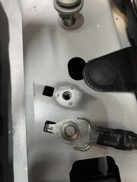
now just clean up make sure you dont forget anything. Put everything back together in the reverse order of these steps.
Verify with forscan that the module is getting 14v with engine on and that the transfer case actuator is working. You can clear all the DTCs and verify they don’t come back. Enjoy the car!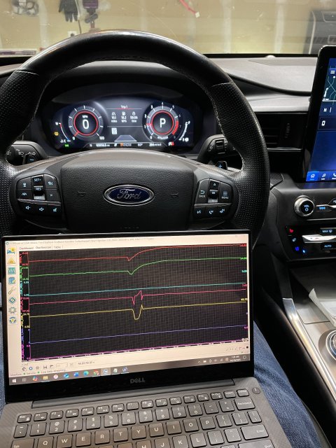
A common issue in these cars in the 2019-2021 build date is a failing ground on the AWD module under the driver’s seat. The metal enclosure of the AWD module is supposed to be grounded by 3 nuts to the body of the car. These standoffs are often covered in paint and in general are just terrible for a proper ground. This failure can be a completely failed ground which means there is an open circuit from the Case to the body of the car. This will cause some set of symptoms, primarily AWD module no longer responding or turning on at all. The failure can also just be an intermittent issue where the symptoms go away and come back occasionally. And finally it can just be that the case has a high resistance path to the body. In this last instance, a multimeter will beep in continuity mode from the case to the body indicating a ground Is present but the resistance is high. The hallmark feature of this issue is that the AWD module gets a lower voltage than all of the other modules. This last case doesn’t seem to be documented anywhere online except in my thread where I diagnosed the issue. In my instance with high resistance ground, it caused the brakes to occasionally fail to work after starting the car and putting the car in gear. VERY SCARY FEELING. Also, I got various frequent ABS codes and random modules failing to respond or getting invalid data. The most worrisome codes it may cause is “transfer case current low” and “transfer case clutches slipping” and “transfer case actuator current low” and “general electrical failure” from the transfer case. And in the ABS module it would report that the transfer case module stopped responding. Every time I scanned for codes i had some different variation of the DTCs.
Diagnosis and Identification:
If you can use Forscan on a computer and log data live with the oscilloscope feature, this would tell you more. The AWD module needs to see close to 12V with engine off and 14v with engine on. If you see 8-10v with engine off or 8-12V with engine on, then you likely have a bad ground. Otherwise if the AWD module isn't being found at all in forscan then your ground might be completely failed.
You can put the drivers seat all the way forward and pull the carpet up pretty easily just enough to see the AWD module. Check continuity from the case to the body of the car. You should have 0 ohms resistance it should be a straight shot from ground to the body.
You can also try wiggling the connector on the AWD module to see if the ground clears up. That temporarily resolved my issues. I have read reports of people removing the harness and putting it back on and the issues going away. When logging live in forscan you can see the voltage correct itself when the ground is restored.
Known issue acknowledged by Ford:
Ford has issued a couple TSBs that i was able to find. Originally they issued a TSB to replace the modules when this happened. They were constantly changing them out and the issues would come back later. Then they discovered the grounding issue. So they issued a (seemingly temporary) TSB to remove the seat and de-pin the ground wire from the harness and splice in a new dedicated ground that terminated at a ring terminal to an M6 bolt in the body of the car under the seat. Finally, it seems to me that this TSB no longer exists anywhere in the Ford database. Now they just fall back to the original TSB to replace the modules but i’m guessing the newer modules have some updated provisions to handle the grounds better internally so it’s not an issue. Personally I don’t want to spend a thousand bucks for the dealership to replace the AWD module when it just needs a ground. So I performed the TSB to add a ground to the existing module.
My Guide for performing TSB 23-2061 for Adding Ground to existing Module:
The official TSB from ford (that no longer exists in their databases) is here: https://www.explorerst.org/attachments/ford-tsb-23-2061-pdf.31859/
things you will need:
the bolt from ford is M6. I used the official Ford bolt but use whatever M6 bolt you like. A 1/4” or M6 ring terminal, i prefer the heat shrink ones. Electrical tape. Some good quality wire. I opted for 14awg. I wouldn’t really go thinner than that. Hard to know what current is expected through it without measuring it in different scenarios. I haven’t smelt anything burning yet so I think 14 AWG should be good (; lastly, you need some way that you feel comfortable to connect this wiire to the ground pin of the AWD module. Honestly this could be as simple as another ring terminal on the nut of the AWD module mounting stud. But because I didn’t fully understand the internal workings of the module I opted to follow the TSB as close as I could. You might be able to get away with a tap splice to the ground wire. If you know the part numbers and know where to get the female pins for the harness that would be the most ideal way. I personally chose to solder the 14AWG wire directly to the existing ground pin. This felt like the best way in my opinion because it means you are not relying on the current flowing through the thin factory wire. But do whatever you feel comfortable with. I’m not responsible for you messing up your harness connector.
getting started:
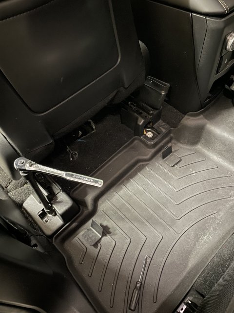
Move the backrest all the way forward so it fits through the door. Then move the whole seat all the way back to expose the front frame bolts.
then remove the plastic covers and unbolt. It’s 13mm.
Then move the seat all the way forward to expose the two rear frame bolts. Remove the plastic covers and unbolt. 13mm again. an extension will help.
now the seat is loose but there is two cables you need to worry about before moving the seat out.
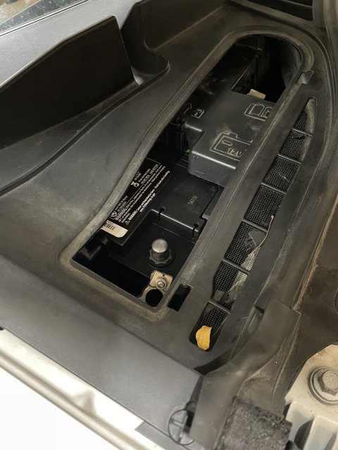
before disconnecting the connectors you need to move the seat halfway forward so the frame rails fit nicely under the butt of the seat. This just helps you fit it through the door. Then disconnect the negative terminal of the battery so you don’t throw a bunch of codes for tampering with the electronics.
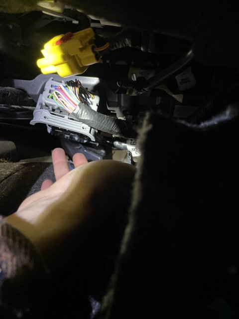
Under neath the seat up under the butt, you have a chunky connector. Press into the connector in the center and there is an arm you need to swing out once the center is pressed in. It’s pretty easy once you figure out how it works.
that body harness is also secured to the seat with a plastic clip so you need to pry it out of the mounting hole.
the following cables look aftermarket and bunk as heck so I don’t know if you will have them… but if you do, cut all the zip ties and expand the cable to it’s full length. There is NO connector to disconnect here… thankfully my cables were super long so i was able to remove the seat still with it attached.
You’re ready to remove the seat now. Optionally you should be able to just push the seat back onto the second row if you fold the second row down. If you proceed to remove it entirely, Be careful not to scratch the plastic trim on the floor or the B pillar. Maybe put a blanket down! It’s heavy but doable alone.
expose the beam and AWD module under the carpet. Pull up that one plastic clip.
here you can see the terrible studs Ford relies on for grounding. You don’t need to remove the module but I did just to get a good look for the photo.
press this center tab and then swing the arm out. Pull the connector off.
this is the pin you will want to depin if you plan to follow my same method of soldering the 14awg wire to the pin.
to remove the red locking Block, it’s not too bad. Use a small flathead to get under the red inside the channel and pry it up. You should squeeze and apply hard pressure with your other hand to the outside of the black housing to help prevent breaking it when prying against it. I broke mine in a few spots but the connector still operates and locks on very good. So it’s not life or death here if you crack something. There are two little channels where you can put the flathead into and there is a good way to get under the red. Use those sides first since the other two of the 4 channels dont give you as mich of a ledge to catch with the screwdriver. It’s really not too bad i thought it was going to be a lot harder.
once you get the red block out, this housing comes off easy. Remove it by pressing this tab and pulling off.
to depin the black and white ground wire pin, its pretty easy too. In between the top and bottom pins you can see the little locking tab deep down holding it in. just pry the plastic tab away from the pin and pull the wire from the back and it will come out. You will want to cut and peel the electrical tape and wrap the factory puts on, expose as much wire as you need. This is how far i went:
i opted to save the red seal thing and just jam the wire through the center. I used a sharp spike tool i had and inserted it through the center and then fed the wire through after the spike. I dont think you need the rubber seal it just helps with corrosion and strain relief but this connector shouldn't see harsh conditions so do what you like.
Solder the new wire to the pin and keep the old wire there. Get it nice and hot, make sure everything is flowed nicely, dont leave a cold joint. Thankfully the connector housing gives you a lot of room for the extra space the solder and wire takes up.
insert the wire to it’s home in the connector listen for the snap of the locking tab, pull to make sure it is secure.
Press the Red locking block back in, it will snap nicely.
Now you want to just give the wires some slack and electrical tape up tightly back to the body harness make it look nice and this will help protect the wires at the pins. Then reinstall the housing and zip tie it on again. just put it back how you found it basically. Check the connection from the AWD module case to the wire you just added.
Then you need to crimp and heatshrink the ring terminal. Measure out how much wire you need and zip tie it in a few spots to the factory harness. You also need to sand the paint (and underlying primer) to expose raw metal on this beam. This is where you will insert your m6 screw and ring terminal. There was no threads in this hole for me but after screwing the bolt in i was able to torque it really well.
now just clean up make sure you dont forget anything. Put everything back together in the reverse order of these steps.
Verify with forscan that the module is getting 14v with engine on and that the transfer case actuator is working. You can clear all the DTCs and verify they don’t come back. Enjoy the car!
Attachments
-
 2 MB Views: 31
Last edited:
-
 12
12
- Show All