• Sign Up! To view all forums and unlock additional cool features

    Welcome to the #1 Explorer ST Forum and Explorer ST community dedicated to Explorer ST owners and enthusiasts. Register for an account, it's free and it's easy, so don't hesitate to join the Explorer ST Forum today!


"Space GhoST"- single turbo ST build

TMac

1000 Post Club
Messages
1,694
Reactions
1,452
Points
262
Location
Knoxville, TN
#1
I've been meaning to put this thread together for some time, the only thing stopping me is the limitations of the site's software- to wit, a person wanting to put together a concise, logical thread of events has to contend with comments, questions, cross-talk and chatter if the subject matter takes some time to complete. Take a look at @UNBROKEN Iconic Silver Build thread. A great thread, yet it's about 20:1 his posts vs others. If someone wanted to read it, it's pretty daunting which is unfortunate.

Edit:
The "two thread" experiment has been a failure. Instead, I have simply laid out place holders for content. Feel free to comment on this thread and feel free to add questions, comments, and criticism to this thread.


So, let's get started....
 

Last edited:
OP
T

TMac

1000 Post Club
Messages
1,694
Reactions
1,452
Points
262
Location
Knoxville, TN
Thread Starter #2
WTF! Two turbos are always better than one...Right???

Quick answer....no. Not so quick answer, it depends on the application. It's pretty easy to see if your mass airflow requirements were larger than a single turbo could support, then yes. But primarily, what people think is that two smaller turbos will "spool" or reach peak boost more quickly than a single turbo. But most of what you assume about why is completely wrong. Most likely you're thinking the smaller turbos rotating components are lighter, or the smaller diameter of those components means they accelerate faster, or because they're smaller, they're more efficient. None of that is necessarily true.

Let's start with apples to apples. Two turbos whose peak efficiency map is centered at 20 lbs/min and a single turbo with the same peak efficiency at 40 lbs/min at the same pressure ratio. Those two turbos will have a rotating mass higher than the single turbo! Not only do their turbine/compressors weigh more, but almost always overlooked is that they also have the downside of double the bearings (friction plays a part of course). Another item often overlooked is clearance. Dual 2" inlets equate to 2 * (2 * pi) = 12.56 inches of circumference. The equivalent 3" inlet 3 * pi = 9.42 inches of circumference. Assuming the clearance is the same (say .020 or 1/2 mm), it's easy to see there is more "leak" on the turbine and compressor sides of twins than a single.

Even so, most people would then say that it's the diameter itself. Whether by math or observation, most people intuitively understand that it's easier to take a 5 lb flywheel with a diameter of 6 inches and accelerate it vs an eqivalent weight 5 lb flywheel with a diameter of 12 inches. Once again, though, why is this? It's because of our friend F=MA. Implicit in that formula is A(cceleration). Even though dimensionless, acceleration implies distance and time- whether millimeters per millisecond or furlongs to fortnights! A single rotation of the 6" flywheel is a distance of its circumference (6 * pi) = 18.85 inches. The equivalent rotation of the 12" flywheel is a circumference of (12 * pi) = 37.7 inches; distance doubled. That's the simplest way to explain a far more complicated subject. Got it? No? Chime in on the questions thread.

So what does this have to do with our smaller diameter turbos? Aerodynamics. Take a look at the speed of the smaller turbo on the compressor map and compare that with the speed of the larger turbo. You will find that the speed of smaller turbos has to be much higher than that of the larger turbo at the same flow rate. This should demonstrate why 2 turbos (or why not 3 or 6) are not "faster spooling" than an appropriately sized single turbo. So why does the ST have two? I'll address this in the next post.
 

Last edited:
OP
T

TMac

1000 Post Club
Messages
1,694
Reactions
1,452
Points
262
Location
Knoxville, TN
Thread Starter #3
Turbo lag. Especially on a 4700+ lb vehicle is to be avoided at all costs. This is especially true from a marketing perspective- after all if you're doing engine downsizing, that last thing you want is your customers not to feel an immediate "kick in the pants" off idle. Especially since the platform in question has been programmed to spend most of it's life at 1500 rpm!. As an aside, if you've ever driven a naturally aspirated big-cammed car, or even say an S2000, you understand that "lag" doesn't just apply to turbochargers.

So how does the ST having twin turbos address this? To achieve maximum compressor "spool" (acceleration), you have four factors: First, you use small turbines. Sure, they will limit performance up high, but due to a small A/R they will accelerate more quickly due to increasing the velocity of the exhaust through the turbine. Second, you move the turbine as close to the flow source as possible to minimize heat (energy) loss. That's why you see the turbines attached to the head. Third, that minimal distance from the exhaust port to the collector (turbine entrance) means that at lower RPMs, a pressure wave is reflected back towards the still open exhaust valve, helping to evacuate the cylinder (if you don't understand this, ask questions!). Fourth, and most importantly, you harness a "pulse" driver. What many may not know is that a 3 cylinder is especially well suited to turbos. That's because you have an engine firing every 240 degrees of crankshaft rotation. What else is happening at 240 degrees of crankshaft rotation? Cam timing. Meaning that only one exhaust valve is open at a time. These "hammer" strikes from the exhaust pressure waves and lack of interference (other open valves, competing flow) help to motivate the turbine faster at lower RPMs. At higher RPMs, it doesn't make any difference.

Now, none of this means that two turbos aren't adequate, but given my penchant for "bang for the buck", the available bolt-on hybrid turbos with the same frame size aren't optimal. Sure, you could go for two "larger" turbos, but that means for any applicable twin setup twice the price and twice the fabrication.

Let's assume you're curious, what's ST capable of?

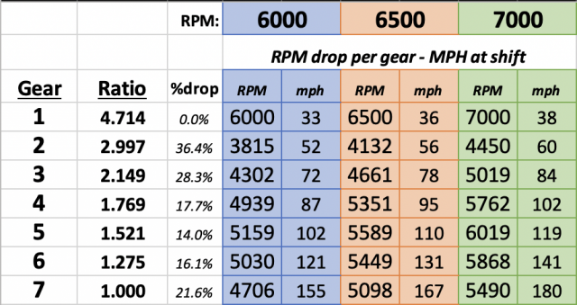
Let's take a look at a spreadsheet I developed with thoughts to a replacement single turbo which will give us the numbers we need to look at compressor charts and to get some concrete math as to what might be expected horsepower-wise from the engine:.
1670184167714.png
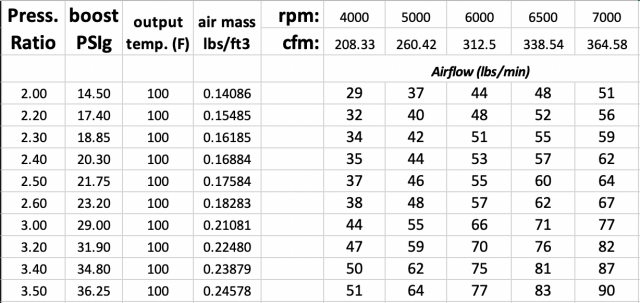
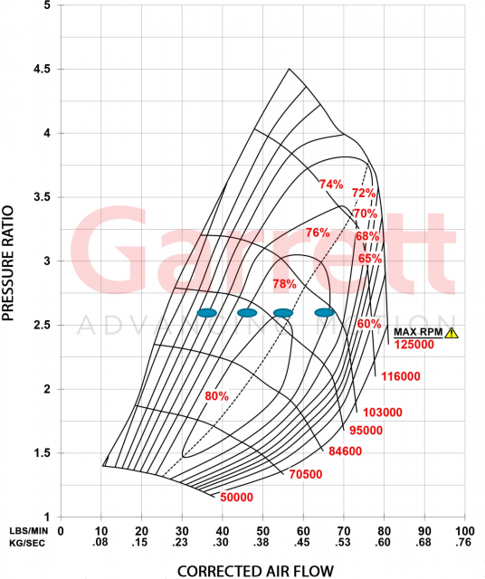
The leftmost column is Pressure Ratio or P/R on your compressor map. It represents the difference between the ambient air pressure and the compressor output pressure and is the "Y" axis on a compressor map.

The second column is the resulting "boost" pressure measured in PSI (gauge) and assumes 1 Bar or 14.5 psi to be ambient pressure. Temp is the output from the intercooler- I've held this the same although it can be adjusted to represent intercooler efficiency and compressor efficiency. If you're curious about this, ask- I'll address compressor efficiency vs temperature rise with equation if anyone cares.

Air mass is the resulting lbs per cubic foot of air. The RPM and CFM column represent the cubic feet of air the engine can injest at those RPM points at 100% VE (curious as to why? Ask questions). The Airflow table then measures the actual mass airflow in lbs/minute for each row. For example, the first row shows at a 2.00 P/R or 14.5 psi of "boost", the airmass at the various RPM points will be 29, 37...48, 51 lbs/min. Each of those mass flow numbers represents the "X" axis on a compressor map. Now as a rule of thumb, we can multiply each of these numbers by 10 to result in HP on gasoline. So, we could expect approximately 290 HP at 4000 RPM, up to 510 HP at 7000 rpm.
 

Last edited:
OP
T

TMac

1000 Post Club
Messages
1,694
Reactions
1,452
Points
262
Location
Knoxville, TN
Thread Starter #4
WTF does my transmission have to do with selecting a turbo???

That my friends is an excellent question and I'll address it. You've probably all heard of the importance of "area under the curve" as it relates to horsepower. In other words, looking at a dyno map, one would look to maximize the area below the HP curve- but remember two things: A dyno does NOT consider the fact that while racing you might occasionally have to shift! Nor does it reflect how your modifications impact the effective HP deltas as you do so.

Bearing that in mind; you also must consider where you start measuring the "area under the curve". Does it start at 1000 RPM? Nope. Unless you're running a diesel, you're probably not spending much time there while racing. To choose the very best turbo, we have to consider the gearing of the transmission so we're operating at the optimal HP range of the engine. As it turns out, even though the programming of the ST would have us spending most of our time at 1500 rpm around town, due to the 10 speed (I'm only going to consider non-overdriven gears, so essentially we have a 7 speed transmission)- the gear ratios are surprisingly performance oriented. Not perfect, but good.

My last post covered the math we need to narrow down our turbo's compressor. All we need to do now is do some math to figure out where the shift points are- this will help us to determine turbine sizing and further constrict compressor options.
1670361328073.png

As you can see from this chart, here are the first 7 gears on the ST measured at 6000, 6500, and 7000 rpms. We'll focus on the center column (6500 RPM). As you'll see, If our shift point is 6500, our RPM will drop in 2nd gear to 4132 RPM. You can continue to follow this down the column noticing that up until 6th gear each succession of gear changes is less and less. This makes up for the increasing load due to aerodynamic drag becoming higher and higher as our speed increases.

Importantly, it also suggests that a turbine that allows full boost by 4100 RPM (we'll leave any discussion of gear specific boost management off the table) is a good candidate for our turbocharger.

It's also important to note that 3rd gear is a drop to 4661 RPM. SInce we have the greatest torque multiplication to the wheels in 1st, followed by 2nd, my approach would be to use a slightly larger turbine- something that might give full boost at 4500 for example. This softens the impact on the drivetrain in 2nd, and also will help to control wheelspin in a drag racing vehicle.

Yes, you will no longer have the full boost of the stock turbos at under 3000 RPM, but it should be clear that if you were truly racing, a setup like this will walk away from the stock turbos, put the drivetrain under less of a shock, and prevent wheelspin. And since I wrote earlier in this post, it's not just the area under the curve, it's the area under the EFFECTIVE curve that matters. In this case, approximately 4100 RPM to redline.

However, since one of the lovely things about going to a single turbo means we'll have multiple turbine A/R selections to choose from, the boost response can be tailored to your particular needs.
 

Last edited:
OP
T

TMac

1000 Post Club
Messages
1,694
Reactions
1,452
Points
262
Location
Knoxville, TN
Thread Starter #5
Here's some info on the math we've developed so far shown on a Garrett G40-900 compressor map. Let's take a look at how to read this information. First, refer to the "blue ovals" on the map. I've used ovals to represent that while the math is sound, actual placement on the compressor map will be slightly variable. These correspond to the pressure ratio on the "Y" axis, and the mass airflow numbers (lbs/min) on "X" ratio from the graph in post #3 corresponding to 4000, 5000, 6000, and 7000 RPM. They are all located at a 2.6 pressure ratio, corresponding with what I would estimate to be the maximum for a 93/30 "pump gas" engine.


1682014263564.png

As you'll notice, the compressor map shows the compressor efficiency islands. Understand that when air is compressed it gains temperature as per Boyle's law. The compressor efficiency number (higher is better), shows how efficient the compressor is at approaching the ideal temp, versus the extra temperature that is introduced into the gas due to the mechanical inefficiency of the compressor. In this case, 80% is the maximum- which is about as high as you can get with current technology.

So, referring back to our graph in post #3, this is a pretty efficient map- 4K engine RPM is around 70% efficient while 7K RPM engine is 78% efficient. Those are very good numbers. Ideally with the right turbine A/R we could hit the peak boost around 4200 engine RPM corresponding with out shift drop in the worst case while staying above 70% efficient on the compressor map.

The other important thing to notice is the compressor RPM numbers which are listed to the right of the efficiency islands and shows the speed of the compressor to produce that amount of airflow. We aren't that concerned about what the RPM is, we are interested that the airflow numbers are within the map, and the speed difference of the compressor as related to the flow figures. Remember that our worst shift drop (see post #4), would be at around 4200 RPM. At that speed looking at the map, our compressor would be turning around 92K RPM. At a max RPM of 7K RPM, we can see that the compressor would be around 103K RPM. This is approx 11K RPM difference for transient response. Not too bad. This is the best match for our engine in the Garrett line.

But, look at the limits, if we stay away from the max RPM curve which is 125K, you can see that this turbo can only produce 75 lbs/minute of flow. It's a bit of Garrett marketing to show this as a "900" (HP) turbo, when is only flows 75 lbs/minute. I assume they are using E85 as the fuel to make this kind of claim!
 

Last edited:
OP
T

TMac

1000 Post Club
Messages
1,694
Reactions
1,452
Points
262
Location
Knoxville, TN
Thread Starter #6
Placeholder
 

Last edited:
OP
T

TMac

1000 Post Club
Messages
1,694
Reactions
1,452
Points
262
Location
Knoxville, TN
Thread Starter #7
The complete system in detail- intake, exhaust, orientation, fabrication details.
 

Last edited:
Messages
339
Reactions
114
Points
37
Location
Oregon
#8
Have you chosen a turbo yet?
 

OP
T

TMac

1000 Post Club
Messages
1,694
Reactions
1,452
Points
262
Location
Knoxville, TN
Thread Starter #9
Placeholder
 

Last edited:
OP
T

TMac

1000 Post Club
Messages
1,694
Reactions
1,452
Points
262
Location
Knoxville, TN
Thread Starter #10
Yes, I've selected a compressor/turbine combo and it will be revealed. Bear in mind that it's a fit for the information that I'll be introducing. There is also a second unit that will be recommended for a slightly different application. Unlike "Lord of the Rings", there is no ONE True Turbo to rule them all!
 

OP
T

TMac

1000 Post Club
Messages
1,694
Reactions
1,452
Points
262
Location
Knoxville, TN
Thread Starter #11
And the winner (winners) is (are)....
 

OP
T

TMac

1000 Post Club
Messages
1,694
Reactions
1,452
Points
262
Location
Knoxville, TN
Thread Starter #12
Bang for the buck- a surprising answer.
 

UNBROKEN

4000 Post Club
Messages
4,204
Reactions
4,896
Points
352
Location
Houston, TX, USA
#13
I like the concept for sure. Plumbing will be interesting…hopefully not too long so there’s not a lot of energy loss between the heads and charger. Ceramic coating or a wrap is in the works I assume?
 

OP
T

TMac

1000 Post Club
Messages
1,694
Reactions
1,452
Points
262
Location
Knoxville, TN
Thread Starter #14
I like the concept for sure. Plumbing will be interesting…hopefully not too long so there’s not a lot of energy loss between the heads and charger. Ceramic coating or a wrap is in the works I assume?
I took a lot of time to plan it out. Plumbing is far easier than it might seem and it's designed for as minimal energy loss as possible. In reality, there is much less concern (power-wise) about energy loss than trying to keep surrounding components from melting! Let's just say it'll be about 10x easier than Kruppas Xona build!

Actually, you inspired me on this to some degree (as did other builds), since for a newcomer to the site it becomes daunting to look at a thread with 1000 posts and then try to sort out the wheat from the chaff. Thanks for the example and input.
 

UNBROKEN

4000 Post Club
Messages
4,204
Reactions
4,896
Points
352
Location
Houston, TX, USA
#15
Ceramic helps a lot but I don’t think it’s as good as the heat wrap and there’s a million turbo blankets on the market. Should be able to keep the stuff you don’t want melted in one piece. lol
 

OP
T

TMac

1000 Post Club
Messages
1,694
Reactions
1,452
Points
262
Location
Knoxville, TN
Thread Starter #16
Placeholder.
 

Last edited:

Dale5403

1000 Post Club
Messages
1,733
Reactions
1,443
Points
262
Location
Mondovi, WI, USA
#17
I plan to follow this hoping to learn some thing.
 

zdubyadubya

Active Member
Messages
813
Reactions
631
Points
232
Location
Utah
Vehicle
2020 ST
#18
I've been wondering for the last two years why you had never posted anything about mods to your own truck.... now i know....hot giggity. looking forward to this immensely.
 

OP
T

TMac

1000 Post Club
Messages
1,694
Reactions
1,452
Points
262
Location
Knoxville, TN
Thread Starter #19
Never in my life have I ever posted a build thread. I never was interested in sharing information. Some of it is in my early days of street racing. My cars were always sleepers- and I enjoyed having them perceived that way. I also enjoy the engineering aspect- nothing wrong with a bolt-on, but I start with looking at the vehicle as a system and then figuring out exactly what to change. I'm sure it'll be controversial and informative!
 

Messages
388
Reactions
336
Points
67
Location
Calgary, AB, Canada
#20
Cool approach from both a thread standpoint and a build concept.

I look forward to following along and learning a few things. There is no reason why a single can’t work if sized and plumbed correctly for the goal you’re looking to achieve.

So, what’s the goal? Are you looking for a certain HP? Torque? Power curve?


Sent from my iPhone using Tapatalk


Top